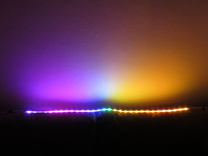
LED strip
I have made a LED strip based on the ATtiny85 / Digispark.
ATtiny85 based
Here's a video, though it looks much nicer in real-life:
What you'll need:
- An ISP programmer, for example another Arduino (or leave out some features)
- A string of 30 LEDs type WS2812
- Two generic push buttons
- Soldering gear
- Source code
Bootloader
I prefer the LED strip with a new bootloader. Flashing your own version has several advantages:
- It is smaller - Micronucleus 2.03 is only 1.5K instead of 2K (meaning you can add more features).
- It is more stable. In my experience uploading a new sketch works in almost all cases using Micronucleus 2.03, while it failed quite often using Micronucleus 1.6.
- When you build your own, you can set the timeout to a much lower value. The default bootloader time (startup delay) is ~6 seconds, but I set it to 1 second (which results in about 1.5 second startup delay).
The main drawback is that you will then need to install sketches manually, as the Micronucleus version provided by Digistump is still version 1.6. Additionally, it assumes it doesn't have that much space so the IDE will complain about lack of space (while it will actually will fit just fine).
You can also install the sketch using no bootloader at all. Use "Upload using programmer" in the Arduino IDE (and select "Arduino as ISP" in the Programmer options) to use it. It means you can use the whole 8K of flash storage for the program. The downside is that it is much harder to install a new program once the Digispark is soldered.
It is easier to flash a new bootloader while the Digispark isn't soldered. You can connect it to the programmer using a row of male header pins and bending the Digispark a bit. Tissue paper appears to work relatively well for this.
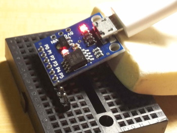
See the instructions here how to install the new bootloader and disable the reset pin. Note that this sketch assumes it can use the reset pin.
Soldering
| pin | function |
|---|---|
P0 |
Button 1: change animation mode |
P1 |
LED strip signal |
P2 |
ground (LOW) for button 1 |
P3 |
ground (LOW) for button 2 |
P4 |
not connected |
P5 |
Button 2: change speed of animation |
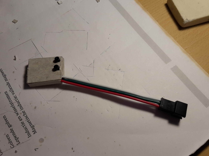
My WS2812 came with two JST connectors on both ends and a separate male JST connector, so I could directly solder the connector to the Digispark. I soldered the red cable directly to the 5V hole and the white to GND after cutting it a bit (~2mm). Cut the cable a bit more for the green connection and leave a bit more bare wire, so that when you solder it to the board (P1) it can easily go under the button (P0 – P2).
Then solder the buttons to the board. They go directly over P0 – P2 and P3 – P5. Most simple push buttons have four connections on the edges, but some push buttons have two connections on the middle of opposite sides. The latter type is preferred because it fits easily on the board. You can also bend two of the pins of a four-pin push button so that it falls exactly in the holes. See below.
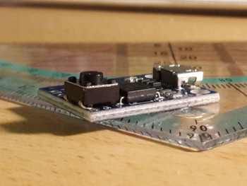
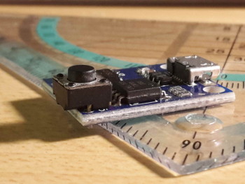
On the left you'll see a modified 4-pin button and on the right you see a 2-pin button. I haven't made photos during soldering, this is just a spare Digispark with the buttons as an example.
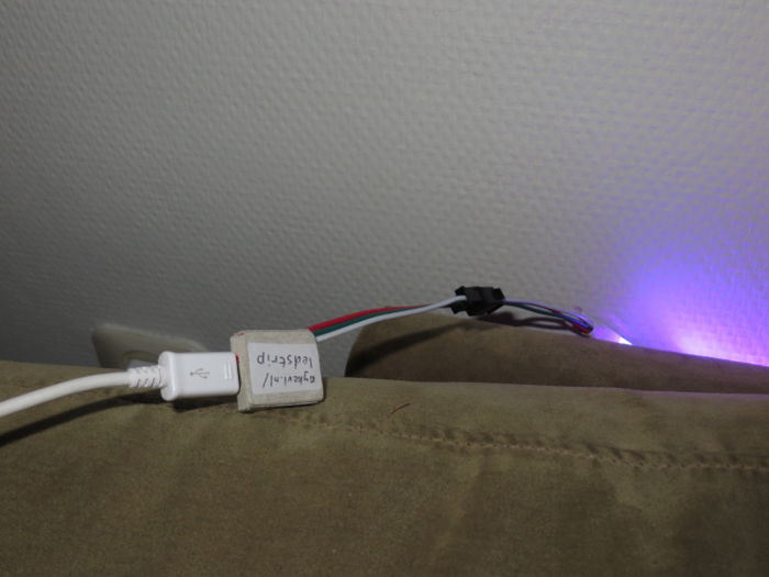
Once you're done, you should of course first test whether the strip actually works. Do both of the buttons work? If the button to change speed halts the sketch and then restarts, it means it resets the device. Disable RESET to use both buttons.
Case
Then of course you don't want bare electronics dangling around.
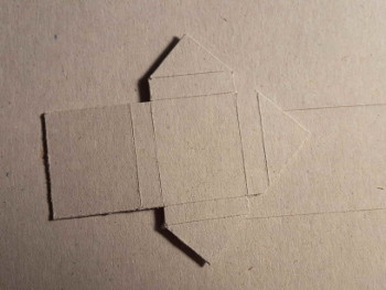
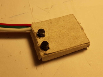
Cut out some cardboard. I used the backside of morning cereals (so you get the gray on the outside). Cut using a Stanley knife or similar. The back and front is 20x25mm and the side is 5mm. In the end it turned out the side (on the button side) was a bit too short - 6mm or 7mm would have been better. I also cut folding edges to make folding a bit easier.
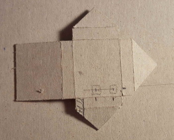
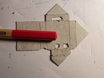
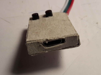
Based on some measurements I cut out some parts so there would be openings for the ledstrip cable, the buttons, and the micro-USB port.
Then I simply used some glue to put it all together. The triangles go to the bottom, and the big untouched 25x20mm area goes over it to hide.